
Xnx Transmitter Installation Manual: A Comprehensive Guide (Updated 12/25/2025)
This manual‚ updated December 25‚ 2025‚ provides comprehensive guidance for installing and utilizing the Xnx Com Transmitter‚ a versatile platform for detecting various gases within industrial settings․
The Xnx Transmitter represents a significant advancement in gas detection technology‚ offering a universal platform capable of identifying virtually all gases commonly encountered in the oil and gas industry․ Introduced by Honeywell in October 2008‚ this transmitter streamlines gas monitoring by consolidating multiple detection needs into a single‚ robust device․
This manual serves as a detailed guide for the installation‚ configuration‚ and maintenance of your Xnx Com Transmitter․ It is designed for technicians and engineers responsible for ensuring safe and reliable gas detection systems․ Understanding the principles outlined within will enable you to maximize the transmitter’s performance and longevity․
The Xnx’s adaptability and comprehensive capabilities make it a crucial component in safeguarding personnel and processes․ This guide will walk you through each step‚ from initial site assessment to ongoing maintenance‚ ensuring a seamless integration into your existing safety infrastructure․
Understanding Xnx Technology & Gas Detection Capabilities
The Xnx Transmitter utilizes advanced sensing technologies to provide broad-spectrum gas detection․ Its core strength lies in its ability to support a wide array of sensors‚ enabling detection of nearly all gases used in the oil and gas sector – from common hydrocarbons to toxic compounds․ This versatility eliminates the need for multiple‚ specialized detectors‚ simplifying system design and maintenance․
The platform’s architecture allows for flexible configuration‚ supporting both individual gas monitoring and multi-gas detection scenarios․ Sophisticated algorithms analyze sensor data‚ minimizing false alarms and ensuring accurate readings․ The Xnx isn’t simply a detector; it’s a comprehensive gas monitoring solution․
Furthermore‚ the Xnx’s supporting sensing technologies are designed for reliability and longevity‚ providing consistent performance even in harsh industrial environments․ This technology is a cornerstone of modern safety protocols․
Key Features of the Xnx Universal Gas Detector
The Xnx Universal Gas Detector boasts a remarkable suite of features designed for optimal performance and user experience․ Its key advantage is its universal sensor compatibility‚ allowing detection of virtually any gas with a single platform․ This reduces inventory and simplifies maintenance procedures significantly․
Advanced diagnostics provide real-time system health monitoring‚ alerting users to potential issues before they escalate․ HART and Modbus communication protocols enable seamless integration with existing control systems‚ facilitating data access and remote management․ The detector’s robust construction ensures durability in challenging industrial environments․
Intuitive configuration and calibration procedures streamline setup and maintenance․ Furthermore‚ the Xnx supports multi-gas detection‚ offering comprehensive safety coverage․ Its flexible alarm management system allows for customized response protocols․

Pre-Installation Considerations
Before installation‚ carefully assess the site‚ verify power requirements‚ and gather necessary tools to ensure a smooth and safe deployment of the Xnx Transmitter․
Site Survey and Location Selection
A thorough site survey is crucial for optimal Xnx Transmitter performance․ Begin by identifying potential gas leak sources and prevailing wind directions․ Select a location that allows for unobstructed gas diffusion to the sensor‚ avoiding stagnant air pockets or direct exhaust streams․
Consider accessibility for maintenance and calibration․ The transmitter should be mounted in a secure location‚ protected from physical damage and extreme weather conditions․ Ensure adequate space around the unit for wiring and sensor connections․
Environmental factors like temperature‚ humidity‚ and potential corrosive substances must be evaluated․ Avoid areas with high vibration or electromagnetic interference․ Proper location selection directly impacts the accuracy and reliability of gas detection‚ safeguarding personnel and processes․
Power Requirements and Wiring Diagrams
The Xnx Transmitter operates on a 24V DC power supply‚ with a consumption of typically 2-5 Watts․ Ensure the power source provides stable and clean power‚ free from significant voltage fluctuations․ Refer to the detailed wiring diagrams provided in Appendix A for specific connection instructions․
Wiring should adhere to local electrical codes and safety standards․ Utilize appropriately sized wiring for the current draw and distance․ Proper grounding is essential for safety and to minimize electrical noise․ Incorrect wiring can damage the transmitter and compromise its functionality․
The diagrams illustrate connections for power‚ signal output (HART or Modbus)‚ and communication lines․ Double-check all connections before applying power․ A dedicated circuit breaker is recommended for the transmitter’s power supply․
Necessary Tools and Equipment
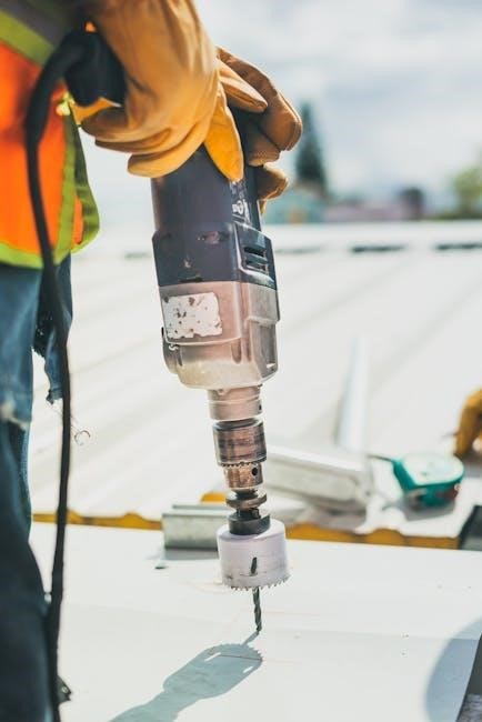
Successful Xnx Transmitter installation requires specific tools and equipment․ You will need a standard screwdriver set (Phillips and flathead)‚ wire strippers‚ and a crimping tool for secure wiring connections․ A multimeter is crucial for verifying power supply voltage and signal integrity․
For mounting‚ a drill with appropriate drill bits for the mounting surface is essential‚ along with a level to ensure proper alignment․ Safety glasses and gloves are mandatory personal protective equipment (PPE)․ Depending on the installation location‚ a ladder or scaffolding may be required․
Calibration gases and a calibration regulator are needed for accurate gas calibration․ A communication interface (HART communicator or Modbus configuration software) is necessary for configuration and networking․ Ensure all tools are in good working order before commencing installation․

Installation Process – Step-by-Step
Begin by carefully mounting the Xnx Transmitter‚ then connect power‚ signal‚ and communication wiring‚ and finally integrate the gas sampling system for optimal performance․

Mounting the Xnx Transmitter
Securely mounting the Xnx Transmitter is crucial for accurate gas detection and long-term reliability․ Select a location that provides optimal gas sampling and accessibility for maintenance‚ avoiding areas with excessive vibration or direct sunlight․
Utilize the provided mounting bracket and appropriate hardware‚ ensuring a firm and level attachment to the chosen surface․ Verify the mounting surface can support the transmitter’s weight‚ especially when considering potential wind loads or seismic activity․
Pay close attention to cable entry points‚ ensuring they are properly sealed to prevent ingress of moisture or dust․ Maintain adequate clearance around the transmitter for airflow and access to connections․ Double-check all mounting hardware is tightened to the manufacturer’s specifications to prevent loosening over time․ Proper mounting contributes significantly to the overall performance and longevity of the Xnx system․
Wiring Connections: Power‚ Signal‚ and Communication
Establishing correct wiring connections is paramount for the Xnx Transmitter’s operation․ Before commencing‚ always de-energize the power source․ Refer to the detailed wiring diagrams provided in this manual and on the transmitter’s labeling․
Connect the power supply‚ observing correct polarity‚ and ensure the voltage matches the transmitter’s specifications․ Signal wiring should be connected according to the configured output type (e․g․‚ 4-20mA‚ HART)․
For communication protocols like Modbus TCP/IP‚ connect the Ethernet cable to a suitable network port․ Proper grounding is essential to minimize noise and ensure signal integrity․ Verify all connections are secure and utilize appropriate cable glands to maintain environmental protection․ Double-check wiring before re-energizing the system to prevent damage․

Gas Sampling System Integration
Integrating the Xnx Transmitter with a gas sampling system requires careful consideration of sample transport and conditioning․ Ensure the sampling point is representative of the monitored environment and positioned according to best practices for the target gases․
Utilize appropriate sampling tubing‚ resistant to corrosion and permeation‚ with minimal dead volume․ Consider installing a filter to remove particulate matter and a moisture trap to prevent condensation․
The Xnx transmitter can directly accept sample gas or be used with a sample system․ Maintain consistent flow rates as specified in the transmitter’s documentation․ Regularly inspect the sampling system for leaks or blockages․ Proper integration ensures accurate and reliable gas detection․
Configuration and Calibration
Proper configuration and calibration are crucial for accurate gas detection․ This section details initial system checks‚ multi-gas calibration procedures‚ and setting appropriate alarm parameters․
Initial Power-Up and System Check
Upon initial power-up‚ carefully verify the Xnx Transmitter receives the correct voltage as specified in the ‘Power Requirements’ section․ Observe the unit’s display; a successful startup will typically show a welcome screen followed by a self-diagnostic sequence․ Allow the transmitter to warm up for the recommended period – usually around 15-30 minutes – to ensure sensor stability․
During the warm-up phase‚ monitor the display for any error messages or fault indications․ Refer to the troubleshooting guide if any issues arise․ Once warmed up‚ navigate the menu to confirm that all sensors are recognized and reporting valid readings․ Check communication status to ensure connectivity with the control system is established․ A successful system check is vital before proceeding to calibration‚ guaranteeing reliable gas detection performance․ Document the initial readings for future reference․
Gas Calibration Procedures (Multi-Gas Support)
The Xnx Transmitter supports multi-gas calibration‚ enabling accurate readings for various gases․ Begin by accessing the calibration menu via the transmitter’s interface․ Select the specific gas you intend to calibrate․ Introduce a known concentration of calibration gas‚ ensuring a proper seal to prevent leaks․ The transmitter will automatically detect the gas and prompt you to confirm the calibration value․
Follow the on-screen instructions carefully‚ adjusting the calibration factor if necessary to match the reference gas concentration․ Repeat this process for each gas sensor installed․ Record all calibration data for traceability and future reference․ Regularly scheduled calibration – as per site safety protocols – is crucial for maintaining the transmitter’s accuracy and reliability․ Verify calibration with a secondary source if possible․
Setting Alarm Levels and Parameters
Proper alarm configuration is vital for ensuring a swift and effective response to gas leaks․ Access the alarm settings menu through the transmitter’s interface․ Define alarm levels – Low‚ High‚ and potentially Very High – for each detected gas‚ based on established safety standards and regulatory requirements․ Configure alarm parameters‚ including latching options (momentary or sustained) and delay times to prevent false alarms․
Assign appropriate alarm actions‚ such as audible alarms‚ visual indicators‚ and relay activation for integration with external systems․ Test alarm functionality regularly to verify correct operation․ Document all alarm settings for future reference and auditing purposes․ Consider site-specific conditions when establishing alarm thresholds‚ and adjust accordingly to optimize safety and minimize disruptions․
Communication and Networking
The Xnx Transmitter supports robust communication protocols like HART and Modbus TCP/IP‚ enabling seamless integration with existing control and monitoring systems for data accessibility․
HART Communication Protocol Setup
Establishing HART communication with the Xnx Transmitter requires careful configuration to ensure reliable data transmission․ Begin by verifying the physical connection between the transmitter and the HART-compatible master device‚ utilizing appropriate wiring and termination resistors as specified in the device’s documentation․
Next‚ configure the transmitter’s HART address uniquely within the network to avoid conflicts․ Utilize a HART configuration tool to access the transmitter’s parameters and set the desired communication settings‚ including baud rate and data format․
Properly define the process variables to be transmitted‚ mapping them to corresponding HART tags for easy identification within the control system․ Thoroughly test the HART communication link after configuration‚ confirming successful data exchange and responsiveness to commands․ Remember to document all settings for future reference and troubleshooting․
Modbus TCP/IP Configuration
Configuring Modbus TCP/IP for the Xnx Transmitter enables seamless integration with existing network infrastructure․ Begin by assigning a static IP address to the transmitter‚ ensuring it resides within the same subnet as the Modbus master device․ Access the transmitter’s configuration interface‚ typically via a web browser‚ and navigate to the Modbus settings․
Define the Modbus slave ID‚ ensuring uniqueness within the network․ Specify the TCP port number‚ commonly 502‚ and configure the communication baud rate․ Carefully map the transmitter’s process variables to corresponding Modbus registers‚ defining data types and scaling factors․
Test the Modbus TCP/IP connection using a Modbus client‚ verifying successful read and write operations․ Document all configuration parameters for future maintenance and troubleshooting․ Secure the network connection with appropriate firewall rules and access controls․
Integration with Existing Control Systems
Seamless integration of the Xnx Transmitter with existing control systems—like Distributed Control Systems (DCS) or Programmable Logic Controllers (PLC)—is crucial for comprehensive gas detection management․ Utilize industry-standard communication protocols‚ such as HART or Modbus TCP/IP‚ to establish a reliable data link․
Configure the control system to recognize the Xnx Transmitter as a data source‚ mapping relevant gas concentration readings to appropriate process variables․ Implement alarm handling routines within the control system to trigger automated responses upon exceeding predefined thresholds․
Ensure proper data validation and filtering to minimize false alarms․ Regularly test the integration to verify data accuracy and system responsiveness․ Document the integration architecture and configuration details for future reference and maintenance purposes․

Maintenance and Troubleshooting
Regular maintenance and swift troubleshooting are vital for sustained Xnx Transmitter performance‚ ensuring reliable gas detection and operational safety within your facility․
Routine Maintenance Schedule
Establishing a consistent maintenance schedule is crucial for the longevity and accuracy of your Xnx Transmitter․ Weekly inspections should include visual checks for physical damage to the housing‚ conduit connections‚ and the sampling system․ Verify that all alarm indicators are functioning correctly during a brief system test․
Monthly procedures necessitate a more thorough examination․ Clean the transmitter’s external surfaces with a damp cloth‚ avoiding harsh chemicals․ Inspect the gas sampling line for obstructions or leaks‚ and confirm proper flow․ Every six months‚ perform a complete functional test‚ including sensor response verification using a known gas concentration․
Annually‚ a qualified technician should conduct a full calibration of all gas sensors‚ replacing filters as needed․ Maintain detailed records of all maintenance activities‚ including dates‚ procedures performed‚ and any observed issues․ Adhering to this schedule maximizes the reliability and safety of your Xnx gas detection system․
Common Troubleshooting Issues and Solutions
Experiencing issues with your Xnx Transmitter? Here are some common problems and their solutions․ “No Power” – verify power supply voltage and wiring connections․ “Sensor Failure” – check sensor calibration and replace if necessary․ “Communication Errors” – confirm HART or Modbus TCP/IP settings and network connectivity․
False Alarms often stem from environmental factors or improper calibration; recalibrate and investigate potential interference․ Low Gas Readings could indicate a sampling system blockage or sensor degradation․ Inspect the sampling line and consider sensor replacement․
If the transmitter fails to respond‚ attempt a system reset․ For persistent issues‚ consult the detailed troubleshooting section in the full manual or contact Honeywell technical support․ Always document the problem‚ steps taken‚ and the outcome for efficient resolution and future reference․
Sensor Replacement Procedures
Replacing sensors on your Xnx Transmitter requires careful attention to ensure accurate gas detection․ First‚ isolate the transmitter’s power supply and depressurize the sampling system․ Next‚ carefully remove the transmitter’s housing‚ following the instructions in the manual’s mounting section․
Disconnect the old sensor from its wiring harness‚ noting the orientation for correct reconnection․ Install the new sensor‚ ensuring a secure fit and proper wiring․ After installation‚ recalibrate the transmitter for the specific gas(es) being monitored‚ using the procedures outlined in the calibration section․
Verify functionality with a known gas source before returning the system to service․ Dispose of old sensors responsibly‚ following local regulations․ Always refer to the complete manual for detailed diagrams and safety precautions․